Drafting Service Files: Attention Glaziers! We Have 4 Questions About BIM for Curtain Walls For You
Updated Feb. 2018: This article was previously published on LinkedIn, where I received several comments. I’ve added this valuable feedback to the article for context.
Here at MP Drafting, we’re involved in many different kinds of glazing projects.
Some require only simple shop drawings. But more and more, we’re tackling projects that require BIM (Building Information Modeling) due to their complexity.
Since we work with glaziers all the time, we’re interested in your opinion on BIM and its effectiveness for your projects. We want to make sure we’re all on the same page.
So if you have any feedback to share after reading this short article, please send me an email or respond in the comments section below.
Your input will help us serve our customers even better, and may also inspire a future educational article on our website.
The first BIM question has to do with Level of Detail (LOD).
1. What is the appropriate LOD for a BIM model?
We typically use an LOD of 350 for BIM models. But we’ve seen a wide range from 250 to 500 (at an LOD of 250 the model is 50% complete, and at an LOD of 500 the model includes 100% of all details necessary for fabrication).
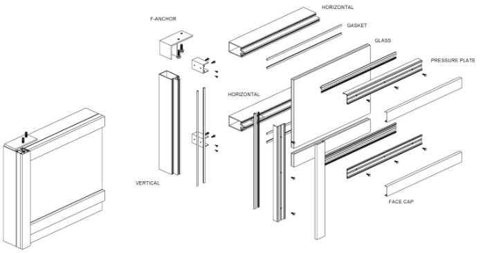
At an LOD of 350, we model the system using the exact system dimensions and locations, and include accessories like sunshades and doors. We also include wind load or dead load clips at this LOD.
As a glazier, what level of detail do you typically see in BIM models? What’s the most detailed project you’ve had to have modeled?
Josh Helm from Dynamic Glass LLC added his two cents on LinkedIn: He recalls using an LOD of 500 for modeling the Toyota HQ in Plano, Texas. His team took 2D shop drawings and made 3D models to send to the CNC shop. In his view, it’s more efficient to send accurately modeled parts to a CNC shop than 2D preps.
Interestingly, he also noted that his field workers all use iPads and iPhones because they work well for manipulating 3D models. Based on what I’ve seen so far, the industry seems to be moving toward making 3D models the norm, rather than 2D shop drawings. This likely has to do with the growing use of CNC equipment.
A BIM makes it much easier to visualize how components fit together, reducing the opportunity for error during fabrication.
2. Sequence and scheduling – should BIM be done before or after shop drawings?
More often than not we’re asked to do BIM prior to creating shop drawings. Is that your experience as well? Or do you typically see requests to create shop drawings before 3D models?
We actually prefer to have the shop drawings done first. And we like to use our own approved shop drawings to create 3D models, because our drawings have already been reviewed and revised by the glazing contractor and the project architect. So by using our own drawings, we can limit the number of rounds of revisions.

3. Clash detection – what are your biggest challenges?
The most common application of BIM is for clash detection of various building components. BIM helps us ensure there’s enough room for all architectural and structural features.
A robust model will let us design workarounds to ensure your glazing system, including all window components, will work with the original design.
So our question for you is what is your greatest challenge when it comes to clash detection? Are there specific glazing components that are often competing for space with other building components?
4. What are some other ways, besides BIM, you would use 3D models?
At MP Drafting, we’ve been involved in projects where 3D models were used for thermal analysis. The drawing below is one example.
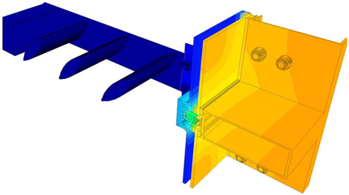
3D models provide insights into how variations in temperature affect connected parts.
We’ve also been asked to analyze challenging building conditions and create fabrication drawings from 3D scans of rough openings.
The photograph below shows a small portion of the Penguin exhibit at the Detroit Zoo. To design it, we created a 3D model of the frames using a 3D scan of the steel supports. Then we used our model to create the shop drawings necessary for fabrication.
Notice that the cornering frame is sloping and almost no piece of glass is square … It’s simply amazing what you accomplish with today’s modeling technology. This entire project was completed using just a 3D scan.
Have you been involved in any projects that would have benefited from 3D modeling?

The Polk Penguin Conservation Center is an award-winning facility with a truly unique exterior design.
Questions?
Thank you for taking the time to read and respond to this article. Your feedback is invaluable to us, so please leave your comments below or send me an email.
We’re actively building up our 3D and BIM resources, so your input will help us decide what to write about next.
Visit our website for more resources on BIM and 3D modeling.