Drafting Service Files: Using Building Information Modeling (BIM) for a Decorative Metal Project [Case Study]
Before I dive into this decorative metal case study, I want to take a moment to thank everyone who provided input to my previous article (if you have yet to read it, you can access it here: BIM for Curtain Walls – 4 Questions We Want to Ask Glaziers). Your feedback is always appreciated. It helps ensure we’re on the right track, offering the right kind of support for your glazing projects.
Your feedback also occasionally inspires a new article idea, which is the case with this one. I decided to build on the previous article and share a specific example of how we use BIM (Building Information Modeling) for decorative metals.
Let’s jump right in.
Using BIM for Decorative Metals
BIM is not just for glazing projects.
The drawing below depicts a parking deck with post-tension cables and decorative metal fins on the building exterior.
The post-tension cables are of course an important feature because they allow for thinners concrete slabs and greater span lengths between support columns, which leaves more room for parking.
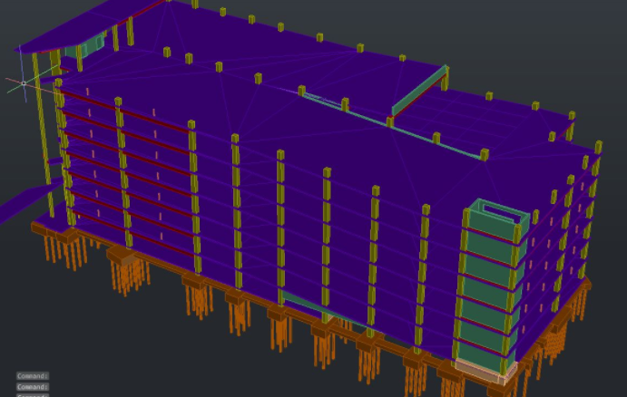
BIM was used to model the structure and all major components, including post-tension cables, concrete slabs, stairwells, and more.
The most important architectural features are the decorative metal fins attached to each floor line of the structure. As you can see from the drawing below, there were thousands of connection points for these fins. The sheer volume presented a real challenge.
Through clash detection exercices, we discovered that hundreds of the proposed metal fins in the original design would be in direct competition for space with the post tension cable ends.
These interferences would have been very difficult to discover without a 3D BIM model. This is just one way BIM reduces the probability of human error.
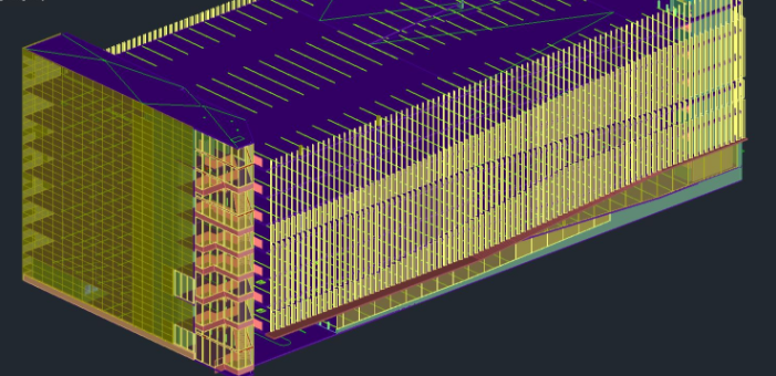
The sheet number of metal fins made clash detection a necessity.
The drawing below gives you an idea of the challenge we needed to work though. The light blue anchor is a modified version of the typical application, designed to span over the end of the cable and prevent obstruction with the metal fins.
Once we solved this interference problem conceptually, we were able to apply a unique solution for each area, being careful that our embed placement drawings were accurate. We made sure the fins kept their designed spacing, even though their attachment points were in the hundreds.
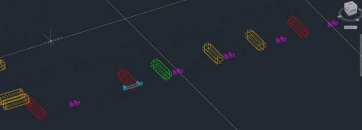
We designed custom anchors (light blue component) to avoid interference between cables and fins.
Finally, with the anchors worked out, we were free to place and model the individual fins as designed by the project architect.
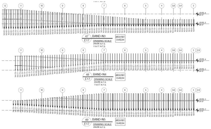
2D drawing of all fins to be fabricated.
This project is a great example of what a skilled drafting team can accomplish with 3D modeling technology. It shows the clear benefit of using 3D BIM for complex designs to identify and solve any interferences early on in the project.
If you’re working on a similar project and need help integrating decorative metal features into the design, I’d love hear from you.
Send me an email if you have any feedback or questions about this project.