Finding Potential Issues in the Shop Drawing Phase (with 5 Examples)
It’s best to catch potential problems in the shop drawing production phase of your project. That way, issues are identified early in the project cycle, leaving plenty of time to address them.
If you know what to look for, you’ll be able to catch most problems in the drawing phase, before they become major issues. So what exactly should you be looking for? It’s important to think through every part of the project, including material procurement, fabrication, delivery, and installation, and try to identify aspects of the design that will lead to complications or confusion down the road. The list of potential issues is long, but we’ve identified five common problems to look for with examples of potential resolutions. This is by no means an exhaustive list, but we think it’s a great start. We plan to write about more examples in the future, so if you have any ideas or suggestions, please let us know.
Example #1: Discrepancies between specifications and architectural drawings
If you notice a difference between specification and architectural drawings, you should note the discrepancy through the formal request for information (RFI) process. Contract documents supercede any other type of project document. And since a formal response to your RFI becomes part of the contract documents, this will protect your company in case the design intent of the architect deviates from what’s provided in the RFI.
It’s also important to note a new RFI submission on your shop drawings. Be specific and note whether it’s a pending or answered RFI. A glazing contractor that we work with always notes RFI items in bold notes on the shop drawings, which brings attention to the fact that an RFI has been submitted.
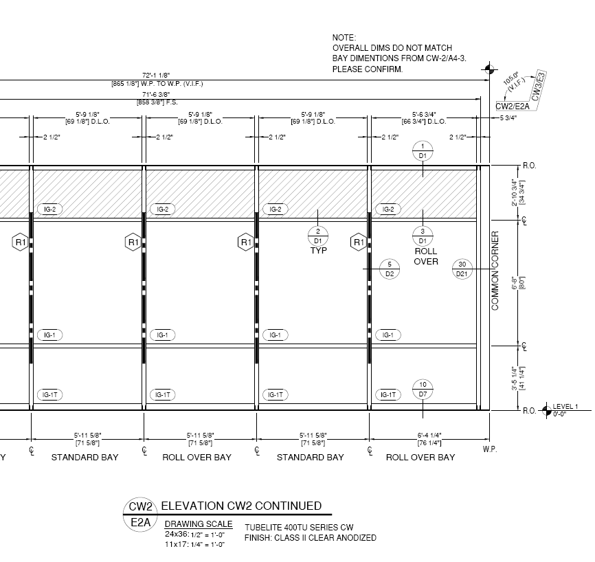
For example, the note in the drawing below draws attention to the fact that the overall dimensions do not match the sum of the individual bay dimensions, and asks the project architect to confirm. While the note stands out at the top of the drawing, it really should be bold and clouded to draw more attention to it.
 Example #2: Missing dimensions in architectural drawings
The standard procedure when dimensions are missing is to leave a note on shop drawings and, if necessary, scale dimensions accordingly (noting the precise dimensions scaled and to what degree). This way, the architect can follow up with the proper dimensions or confirm that your scaled dimensions are correct.
This rule applies to any type of dimension required for glazing systems, including reference and coordination dimensions. For example, frame location dimensions from column lines and horizontal placements in relationship to a floor line sometimes require scaling, but they should always be verified with the architect.
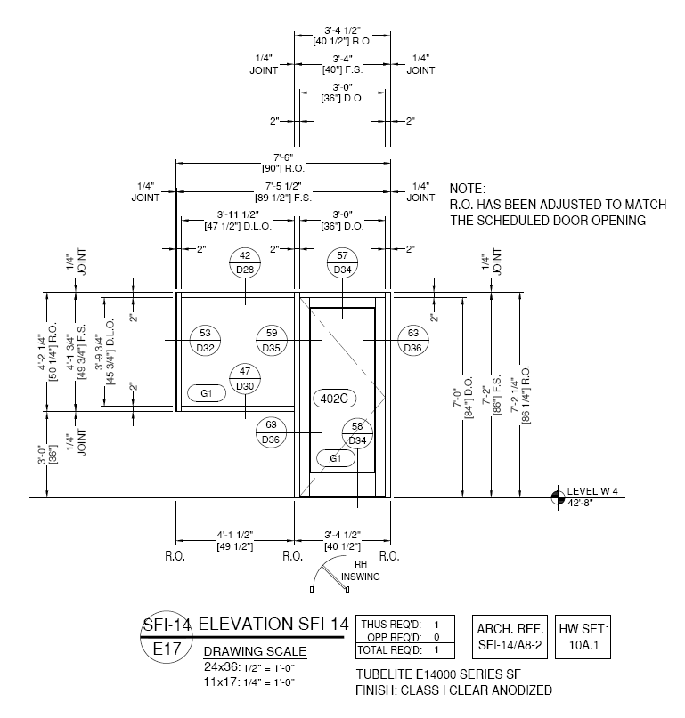
The note on the right in the drawing below points out that the door opening height shown matches the door schedule, but the rough opening dimension had to be adjusted. This is a common problem because architects do not always take joint sizes into account when determining rough openings.
 Example #3: System sealant and drainage issues
Every good project manager should understand how the system weeps and drains. It’s critical to review these items on shop drawings, including how the system interacts with the surrounding conditions of the building. For example, if a decorative building element is blocking weep holes or won’t allow water to drain away from the framing, it’s imperative to BOLDLY note this issue on the drawings so the architect can provide you with a solution.
A similar issue often arises if the architect shows caulk joints in an improper location. Always refer to installation instructions and manufacturer details for the correct location and show them correctly in the shop drawings, while of course noting the discrepancy so the architect can confirm.
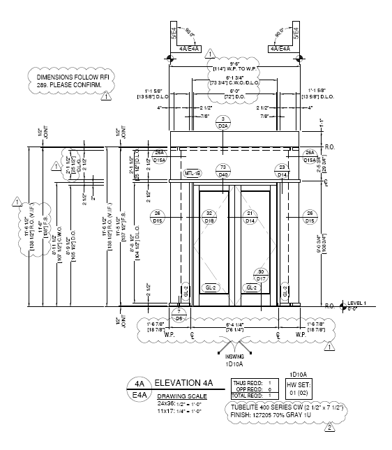
This example displays a note to confirm that dimensions follow RFI 289 for the frame and prompts the architect to confirm this was done correctly.
Example #4: System anchoring and movement issues
System anchoring issues can be complicated and may require a professional engineer’s assistance. Any anchor and system movement issues must be noted early on the design process. It can be complicated because there isn’t always a gold standard for anchoring (the type and location of anchors for your frame can vary based on building conditions, frame configurations, and personal preference). Including your intentions in the shop drawings early on in the process gives the architect and building engineer enough time to review the drawings and, if necessary, provide a new solution.
For example, if you have a couple of options for where to anchor your frame, such as a floor line or I-beam under the floor slab, and the architectural drawings don’t clearly show which option to use, use your best judgement and include a bold note for the project architect and engineer to confirm.
You also need to add a note to shop drawings any time an anchor penetrates a flashing and/or membrane designed to control water, such as a head/brick flashing. If there’s enough structure behind the frame, a strap anchor can be an acceptable solution (but, again, don’t forget to add a note to get confirmation). We’ve seen architects actually revise the flashing design to allow anchors in standard locations, but it doesn’t happen very often.
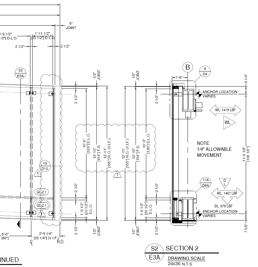
The drawing below shows anchor locations with applicable loads and a note about the maximum movement the system can handle. While the note stands out, it could be more detailed. For example, it would be more effective if it read:
NOTE: SYSTEM AS DRAWN AND CONFIGURED CAN ONLY ALLOW ¼” OF STRUCTURE LIVE LOAD MOVEMENT.
In this case, we also submitted the drawings to the general contractor for review by the building engineer to confirm the structure will not move more than ¼” under design loads.
 Example #5: Door and hardware-specific issues
The number of door and hardware-specific issues is almost endless due to the countless configurations and hardware types available. It’s always great to have some knowledge and experience with door hardware and functionality, but, luckily, most hardware vendors are very knowledgeable and offer review services to check your project for any issues. Some common issues that are worth noting on shop drawings include:
- Door hardware incompatibility with door rail sizes
- Door swing issues (such as inswing exterior doors)
- Electronic hardware (specifically, who is providing which components)
- Missing information such as handle or lock locations relative to the walking surface
- Incorrect door types shown for specific applications
We recently had a great example come through our office: an architect showed standard doors on a 3rd-floor terrace as inswing doors, which are not recommended for this application because of the potential for heavy water and air infiltration. Purpose-built terrace-type doors are the correct choice for this application, but they’re much more expensive than standard aluminum entrances. We discussed the issue with our customer and added a note on the drawings at the location of each door.
The customer followed up with the general contractor and the architect decided to leave the doors as is. Of course, when the owner started experience water and air infiltration, they weren’t too happy. But because we raised the issue with the general contractor and added a note on the drawings, the glazing contractor was able to secure a change order for the replacement doors. Another alternative is to install an outswing door with door stops to provide a positive surface into which the door can close.
Stay tuned for more examples
We’ll be publishing a follow up to this article with more examples of issues that should always be noted on shop drawings, so stay tuned. If you have any ideas for the next article or questions about this one, please don’t hesitate to reach out!